7 · DC Circuits, RC Transients, and Dielectrics
Course index · Previous · Next
1. Circuit variables, meters, and ground
Current describes charge flow; a node potential describes electrical energy per charge relative to a reference. A source supplies energy, resistors dissipate it, and capacitors store it.
| Element / instrument | Connection or equation | Meaning |
|---|---|---|
| Ammeter(电流表) | In series; ideally \(R_A=0\) | Measures branch current with negligible added voltage drop. |
| Voltmeter(电压表) | In parallel; ideally \(R_V\to\infty\) | Measures a potential difference while drawing negligible current. |
| Ground(接地) | Choose a reference node \(V=0\) | An earth connection can exchange charge; circuit reference ground need not be earth. |
| Resistor | \(v_R=Ri\) | Passive voltage drop in the direction of conventional current. |
| Capacitor | \(q=Cv_C\), \(i=C\,dv_C/dt\) | Fixed linear capacitance, with current entering the labeled positive terminal. |
A real meter changes the circuit. Its effect is small when \(R_A\) is much smaller than the resistance in the measured current path, or \(R_V\) is much larger than the circuit's resistance seen at the voltage terminals. The classroom's approximately 100:1 comparison is a useful 1%-scale loading estimate, not a universal instrument specification.
2. Electromotive force and Kirchhoff's rules
An emf source uses chemical, mechanical, or other energy to move charge against the electrostatic force internally:
Emf(电动势) is energy per charge, not a mechanical force. An electrostatic field does zero net work around a closed path; the source's nonelectrostatic action supplies the energy dissipated elsewhere.
- Junction rule: \(\sum i_{\mathrm{in}}=\sum i_{\mathrm{out}}\) when no charge accumulates at the node.
- Loop rule: the signed voltage rises and drops sum to zero in the lumped circuit model, with any induced emf included explicitly.
| Traversal | Signed voltage change |
|---|---|
| Resistor along assumed current | \(-iR\) |
| Resistor opposite assumed current | \(+iR\) |
| Ideal source from \(-\) to \(+\) | \(+\mathcal E\) |
| Capacitor from labeled \(+\) to \(-\) | \(-q/C\) |
Assign current directions first, write independent node/loop equations, and solve; a negative current means the actual direction is reversed. Complicated networks cannot always be reduced by inspection to series and parallel parts.
For a battery of internal resistance \(r\) driving load \(R\),
The terminal voltage differs from the emf while current flows. The displayed formula describes a discharging battery; current driven into its positive terminal reverses the internal-drop sign.
Series and parallel combinations
| Connection | Resistors | Capacitors |
|---|---|---|
| Series | \(R_{\mathrm{eq}}=\sum R_j\); same current | \(1/C_{\mathrm{eq}}=\sum1/C_j\); equal charge magnitudes for neutral intermediate nodes |
| Parallel | \(1/R_{\mathrm{eq}}=\sum1/R_j\); same voltage | \(C_{\mathrm{eq}}=\sum C_j\); same voltage |
These are ideal lumped-element relations; initial charge on a floating intermediate node must be accounted for separately.
3. Electrical power and capacitor energy
With the passive sign convention, absorbed power is \(P=vi\). A resistor converts electrical energy into heat:
For a source driving current out of its positive terminal, delivered power is \(\mathcal Ei\). In a simple steady circuit, \(\mathcal Ei=i^2(R+r)\); average carrier kinetic energy need not grow while the lattice heats.
Charging a linear capacitor requires progressively more work because \(v=q/C\) increases:
Using \(qv\) for the stored energy overcounts the work: the voltage was not equal to its final value throughout charging.
4. RC charging and discharging(充放电)
For a series resistor, capacitor, and constant ideal source, let \(q\) be the charge on the capacitor plate receiving positive current, so \(i=dq/dt\):
For any initial charge \(q_i\),
For an initially uncharged capacitor,
At \(t=\tau_C\), charge reaches \(1-e^{-1}\approx63.2\%\) of its final value. At long times the ideal capacitor carries no DC current. Finite \(R\) prevents its voltage from jumping instantaneously.
For source-free discharge from \(q_0\),
The minus sign refers to the retained charging-current direction. The discharge current magnitude is \(q/(RC)\).
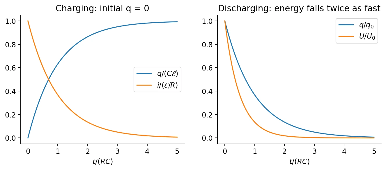
Energy checks:
Charging from zero through a resistor with a constant source supplies \(C\mathcal E^2\): half remains in the capacitor and half is dissipated. This result assumes the ideal RC setup, not every possible charging protocol.
5. Energy stored in an electric field
For parallel plates in vacuum, \(C=\epsilon_0A/d\), \(v=Ed\), and the gap volume is \(Ad\). Thus
The vacuum expression applies locally beyond the parallel-plate example, and total field energy is \(U_E=\int u_E\,d\mathcal V\) when finite. An ideal point charge has a divergent self-energy; interaction energies exclude that singular self-contribution.
6. Dielectrics: free and bound charge(自由电荷与束缚电荷)
A dielectric is an insulator whose charges respond to an applied field:
- Polar molecules have permanent dipoles. A field biases their otherwise thermally disordered orientations.
- Nonpolar molecules acquire induced dipoles through small relative displacements of positive and negative charge.
Both mechanisms produce polarization; the material remains approximately neutral in its bulk if polarization is uniform. Bound charges at its surfaces generate a field opposing the original field in the filled parallel-plate geometry. Strong enough fields can cause dielectric breakdown(介质击穿) and conduction.
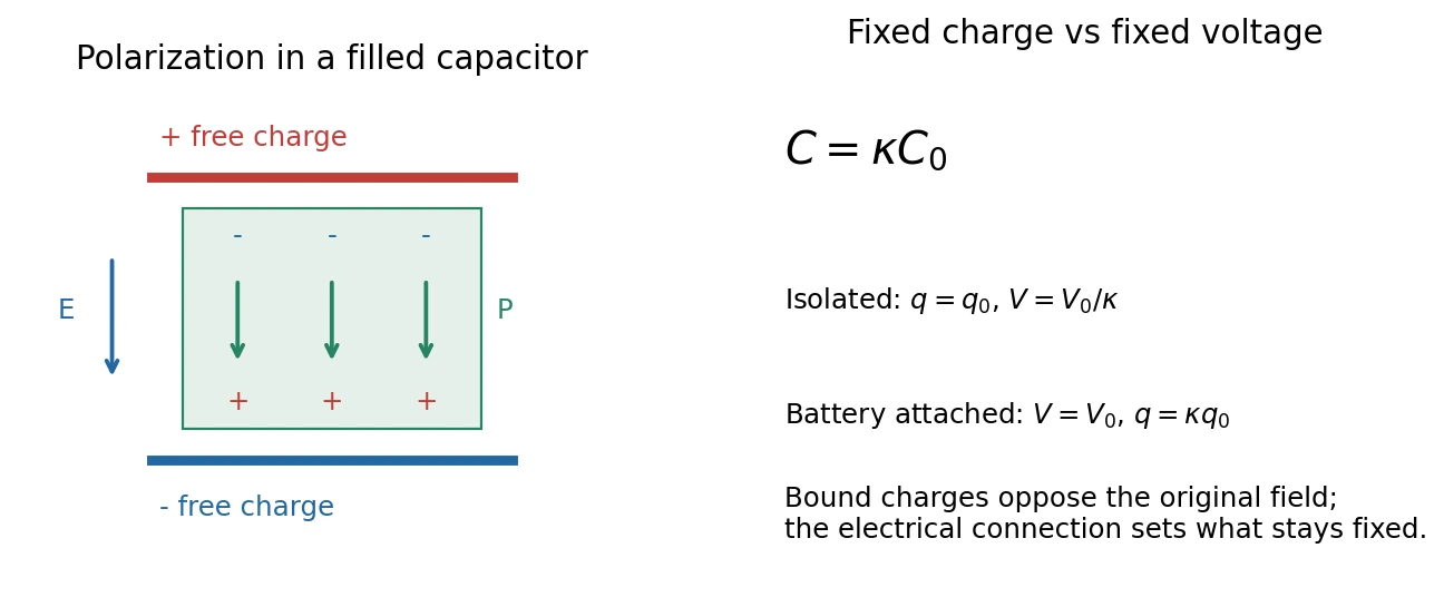
For a homogeneous linear isotropic dielectric,
| Fully inserting a dielectric | Isolated capacitor: fixed \(q\) | Connected to ideal battery: fixed \(v\) |
|---|---|---|
| Capacitance | \(\kappa C_0\) | \(\kappa C_0\) |
| Field and voltage | \(E_0/\kappa\), \(v_0/\kappa\) | \(E_0\), \(v_0\) |
| Free plate charge | \(q_0\) | \(\kappa q_0\) |
| Stored energy | \(U_0/\kappa\) | \(\kappa U_0\) |
中文提示:先判断电荷还是电压保持不变,再讨论电场与能量。接着电池时,电池也参与能量交换,不能只看电容器的能量变化。
For fixed free charge \(q\), the bound face-charge magnitude is \(q_b=q(1-1/\kappa)\). The ordinary Gauss law counts all enclosed charge:
Replacing \(\epsilon_0\) by \(\epsilon\) is justified only with the appropriate homogeneous linear material model and boundary conditions. Static \(\kappa\) is not automatically the optical-frequency permittivity used in class 15.
7. Polarization and electric displacement
The start of class 8 completes this part. Polarization is dipole moment per unit volume:
Its bound charge densities are
where \(\hat{\mathbf n}\) points outward from the dielectric. Uniform \(\mathbf P\) gives no bulk bound charge but can give nonzero surface charge.
Define electric displacement(电位移) by
For linear isotropic response, \(\mathbf P=\epsilon_0\chi_e\mathbf E\), \(\kappa=1+\chi_e\), and \(\mathbf D=\epsilon\mathbf E\). The definition of \(\mathbf D\) is more general than this constitutive relation. It is not generally “the field from free charges alone”; it is an auxiliary field whose divergence counts free charge.
In a linear nondispersive medium, the combined reversible electric/material energy density is \(u_E=\tfrac12\mathbf E\cdot\mathbf D\). Nonlinear, dispersive, or hysteretic media require a more careful energy treatment.
Related homework(知识点应用)
- Ch. 7, Ex. 3 · Wheatstone bridge.
- Ch. 7, Ex. 5 · Three-resistor RC transient.
- Ch. 7, Ex. 9 · Capacitor force including battery work.
Sources and checks
Lecture 7 pp. 3–24: circuits and RC response; pp. 25–32, 43–46: energy and dielectric mechanisms; pp. 36–42: network combinations. Polarization formulas come from the first approximately 30 minutes of class 8. Check meter loading, loop signs, \(q\)-versus-\(v\) constraints, and the distinction between free and total charge.