12 · Inductance, RL Circuits, and Magnetic Energy
Course index · Previous · Next
1. Flux linkage and self-inductance(自感)
A current creates magnetic flux through its own circuit. For fixed geometry and linear magnetic response,
For \(N\) turns all linking the same flux, \(\Lambda=N\Phi_B\). The total flux linkage, not one turn's flux, defines the inductance. The slides initially assume vacuum/air cores without nearby magnetic materials; in general \(L\) depends on material response as well as geometry and can become nonlinear.
Long solenoid
With \(n=N/\ell\), cross-sectional area \(A\), and negligible end fields,
so
The square in \(N\) reflects both a stronger source field and more turns linking that field. The expression assumes a tightly wound solenoid with length much larger than radius.
2. Self-induced emf and terminal voltage
Faraday's law gives
for constant \(L\). The self-emf opposes the change in current: it opposes an increase but supports the existing current during a decrease.
With current entering the labeled positive terminal, the ideal inductor's passive terminal voltage is
The opposing emf and the terminal voltage use different sign conventions; they are not competing laws. A winding with resistance \(r\) has \(v=ri+L\,di/dt\). In a nonlinear core one must use \(d\Lambda/dt\), not assume a constant \(L\).
The winding's interior field can be nonconservative. Terminal voltage is a lumped-circuit quantity defined with a consistent lead path outside the strongly changing-flux region; it is not proof that a global electrostatic potential exists throughout the coil.
3. RL switch-on and decay
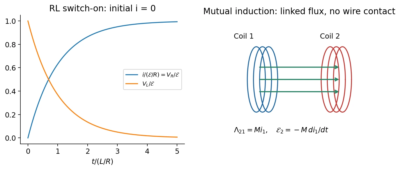
For an initially current-free series circuit,
The general constant-source solution is
For \(i(0)=0\),
At \(t=0^+\) the inductor supports the applied voltage and current is still zero. At long times an ideal inductor has zero voltage drop and acts as a DC short circuit. Current cannot jump without an impulsive voltage.
If the source is removed while a closed resistive discharge path remains,
Opening an inductive circuit without a suitable path can instead generate a large voltage; an ideal exponential-decay formula presupposes the specified discharge circuit.
| Feature | RC circuit | RL circuit |
|---|---|---|
| Time constant | \(RC\) | \(L/R\) |
| State continuous for finite drive | Capacitor voltage / charge | Inductor current |
| Energy stored | \(q^2/(2C)\) | \(Li^2/2\) |
| Ideal DC limit | Capacitor open | Inductor short |
4. Magnetic energy and energy density
Multiply the RL equation by \(i\):
The source supplies heat plus increasing magnetic energy. Integrating \(dU_B=Li\,di\) gives
For an ideal long solenoid occupying volume \(A\ell\),
The vacuum field energy density is therefore
The magnetic expression is not restricted to a solenoid in vacuum. In a linear reversible nondispersive medium, the corresponding magnetic/material energy is \(\tfrac12\mathbf B\cdot\mathbf H\); hysteretic media require accounting for dissipation rather than blindly substituting \(\mu\).
5. Mutual inductance(互感)
Current \(i_1\) in coil 1 can link flux through coil 2:
For fixed reciprocal linear configurations, \(M_{21}=M_{12}=M\). Coil orientation sets its sign; reversing one winding reverses the signed coupling. If geometry changes, differentiate \(Mi_1\) rather than treating \(M\) as constant.
Small coil at the center of a larger coil
Let \(R_2\ll R_1\) for concentric coplanar coils of \(N_1,N_2\) turns. Across the small coil, the larger coil's field is approximately uniform:
The classroom also computes the reverse linkage. Approximate coil 2 as dipole \(\mu_2=N_2i_2\pi R_2^2\). In its equatorial plane far from the small coil, \(B_z\simeq-\mu_0\mu_2/(4\pi r^3)\). The return flux outside radius \(R_1\) is
Zero total planar flux gives the opposite flux through the larger loop. Multiplying by \(N_1\) yields the same \(M\). Integrating the dipole approximation down to \(r=0\) would be invalid; the outside-return-flux argument avoids its singularity.
6. Classroom applications
- Transformer: linked changing flux transfers energy between electrically isolated circuits. For ideal windings sharing the same flux, voltage magnitudes satisfy \(|v_2/v_1|=N_2/N_1\); steady DC produces no sustained secondary induction. Real transfer depends on coupling, loading, and losses.
- Magnetic measurement: a known drive winding sets an applied-field scale; a pickup winding measures \(-N\,d\Phi_B/dt\). Integrating the pickup signal recovers changing flux, permitting a calibrated magnetic response or hysteresis measurement.
- Signal coupling: mutual induction can couple AC signals without a direct conductive connection. It does not imply complete isolation from every parasitic capacitive or magnetic disturbance.
中文提示:自感是本回路的电流改变本回路的磁通;互感是一个回路的电流改变另一个回路的磁通。两者都遵循法拉第定律,区别在于磁通由谁产生。
Related homework(知识点应用)
- Ch. 12, Ex. 5 · Current reversal, voltage polarity, and energy.
- Ch. 12, Ex. 7 · Internal inductance and flux linkage.
- Ch. 12, Ex. 9 · Mutual inductance and source work.
Sources and checks
Lecture 12 pp. 4–15: inductance and RL response; pp. 17–23: energy; pp. 24–28: mutual induction. The classroom adds magnetic measurement, transformer use, and the reverse-linkage calculation. Check flux versus flux linkage, emf versus passive voltage, and the fixed-geometry/linear-response assumptions.